One day an excellent idea arose in our company: to create something connected with augmented reality. We decided to create a mobile app for our office guests. It was supposed to make visiting our office more informative and impressive. For example, the app was to help a visitor find their way around our premises. It was also supposed to recognize markers and give hints as to where different rooms are situated.
So, we decided to implement the following functions:
- Marker recognition: markers are caught by the camera and additional data is shown;
- Face recognition: the name and position of a person seen by the camera are shown;
- Navigation: the current position and main directions (meeting rooms, exits, etc.) are displayed.
Info markers
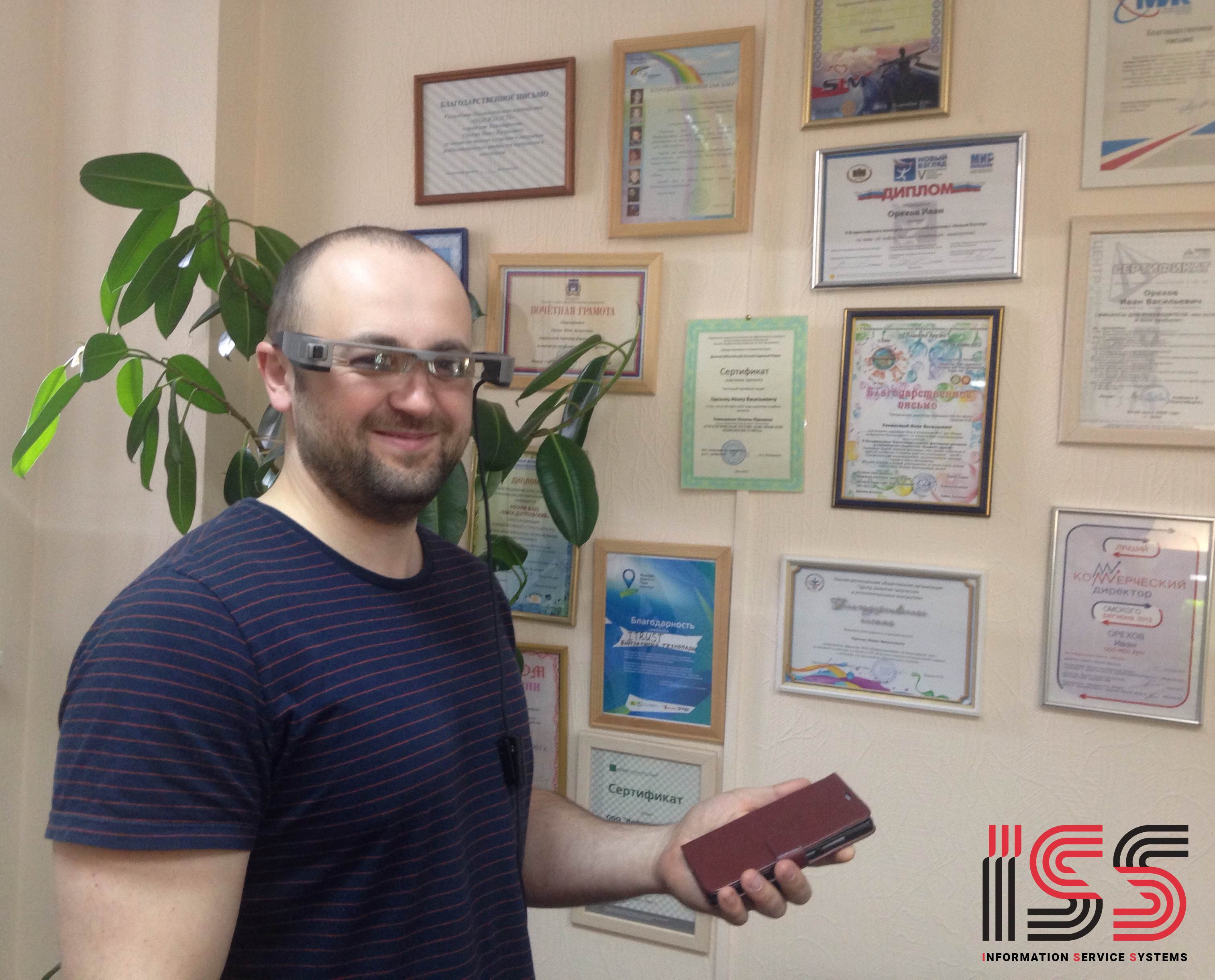
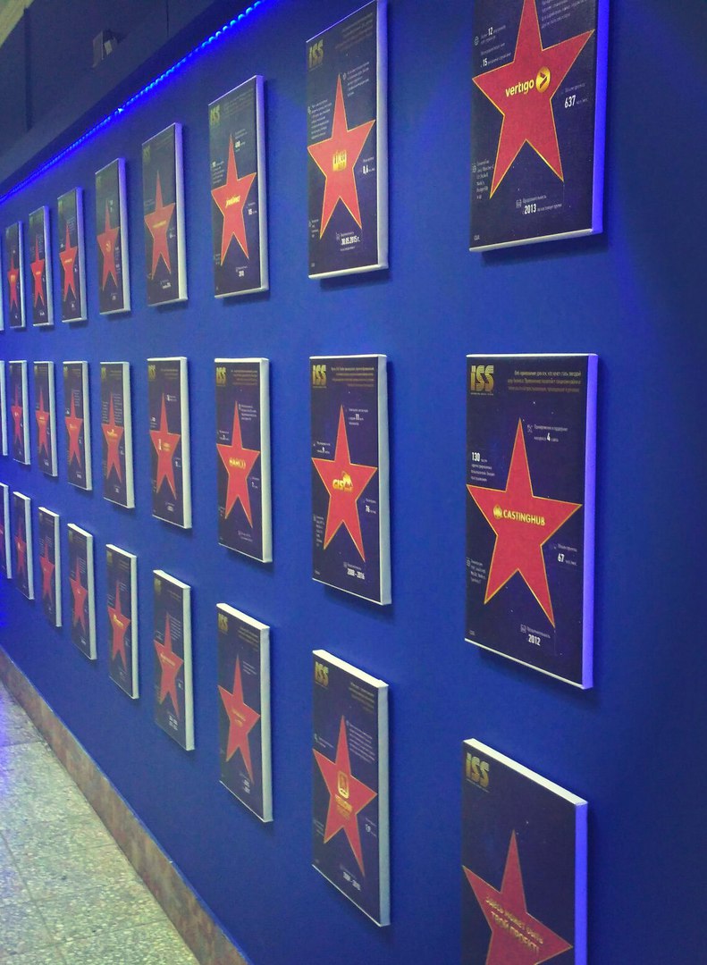 The first thing we did was info marker recognition. In our company we have the "Wall of Fame". This is a wall with logos of the projects we have completed. It would be nice to add a full description for every project: what it is about, technologies used, the team, etc.
The initial idea was very simple: to catch a project logo and then to show the information. Two tasks should be solved to do that:
The first thing we did was info marker recognition. In our company we have the "Wall of Fame". This is a wall with logos of the projects we have completed. It would be nice to add a full description for every project: what it is about, technologies used, the team, etc.
The initial idea was very simple: to catch a project logo and then to show the information. Two tasks should be solved to do that:
- Find and recognize a marker;
- Evaluate its position relative to the camera.
To save time and avoid reinventing a wheel, we looked for a ready solution. Vuforia is an indisputable hit here. But it isn't free. So, we took another library – ARToolkit. The documentation is far from being perfect, the source code isn't readable in some places. … But it works!
The first step brought about the first trouble: nicely decorated logos are… decorated too nicely! The stars are very large, the logos of the projects are low-contrast and small. It makes all logos look the same.
So, we used another approach: framed markers. This is a black-and-white image placed inside a black border. The width of the border is half the image size. It is less esthetical, but it is easy to be caught.
ARToolkit flow
At first, initialize ARToolkit:
ARToolKit.getInstance().initialiseNative(this.getCacheDir().getAbsolutePath());
Then add a marker:
Int markerId = ARToolKit.getInstance().addMarker("single;"+markerFileName+";80");
ARToolkit is able to track multiple markers in the same frame. It assigns an ID to every new marker we add. This ID is used later to query the position of the marker. We store this ID in the markerId variable.
The string we pass to addMarker may have the following formats:
- single;data/hiro.patt;80 – a single marker from data/hiro.patt file. Its physical size is expected to be 80х80mm;
- single_buffer;80;buffer=234 221 237… – a single 80х80mm marker, but the content is right in this string, not a separate file;
- single_barcode;;80 – barcode marker. Looks like not implemented: ARPattern.cpp.
- multi;data/multi/marker.dat – multiple markers treated as a single one. Each marker is described in a separate file. The file passed here contains a list of markers and their mutual positions.
- nft;data/nft/pinball – an ordinary colored image. ARToolkit can recognize such images too. The SURF is used in this case.
We used the first case – a single marker.
A marker is described by a plain text file. It contains three blocks separated from each other by empty lines. Each block describes a single channel (red, green and blue) of a wanted image. It contains 16 rows with 16 numbers from 0 to 255.
So, to describe the marker
rgb(r11,g11,b11) … rgb(r1_16, g1_16, b1_16)
…
rgb(r16_1,g16_1,b16_1) … rgb(r16_16, g16_16, b16_16)
we should create a file like this:
r1_1 r1_2 … r1_16
...
r16_1 r16_2 … r16_16

g1_1 g1_2 … g1_16
...
g16_1 g16_2 … g16_16

b1_1 b1_2 … b1_16
...
b16_1 b16_2 … b16_16
Ok, we found a marker. Now we need the info about it to be displayed. Not just as a slide – we want the info to follow the marker as if it was "glued" to the real one.
To achieve this, we need to align the info with the marker on the screen. ARToolkit provides a way to do it: draw the info with OpenGL in 3D and setup a projection that gives a proper info-to-marker alignment.
The OpenGL projection is described by 4×4 matrix. Below we will describe how to build it for AR glasses in detail. As for now, ARToolkit makes all maths for us. All we need is to pass the video frame size:
@Override
public void cameraPreviewStarted(int width, int height, int rate, int cameraIndex, boolean cameraIsFrontFacing) {
(ARToolKit.getInstance().initialiseAR(width, height, "Data/camera_para.dat", cameraIndex, cameraIsFrontFacing));
}
And the frame itself:
@Override
public void cameraPreviewFrame(byte[] frame) {
ARToolKit.getInstance().convertAndDetect(frame);
}
Recall for completeness: clear all after
@Override
public void cameraPreviewStopped() {
if (ARToolKit.getInstance().isRunning())
ARToolKit.getInstance().cleanup();
}
So, now ARToolkit has a video frame, its size and a set of markers. When a new frame is delivered, ARToolkit performs the following steps:
| 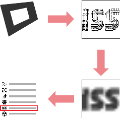 | 1. Find all black borders. This is a step where unsightly black border is required. It is easily distinguishable from ordinary objects; 2. Perform perspective transform that maps an image inside a border to a square aligned with horizontal and vertical axes; Downscale the image to 16×16 size. This is a "fingerprint" of the marker; 3. Compare this fingerprint with known samples. If enough similarity is found, then the marker is recognized. |
|---|---|
| 1. Find all black borders. This is a step where unsightly black border is required. It is easily distinguishable from ordinary objects; 2. Perform perspective transform that maps an image inside a border to a square aligned with horizontal and vertical axes; Downscale the image to 16×16 size. This is a "fingerprint" of the marker; 3. Compare this fingerprint with known samples. If enough similarity is found, then the marker is recognized. |
|---|---|
Now let us check if the marker is found:
ARToolKit.getInstance().queryMarkerVisible(markerId)
And the last in terms of order, but the first in terms of importance – where the marker is:
float[] data = ARToolKit.getInstance().queryMarkerTransformation(markerId);
As a result, we have 4×4 matrix. Pass it to OpenGL and voila – we are able to draw 3D objects in the marker coordinate system. Everything we drew in that way behaves as if it was glued to the real marker.
AR Glasses
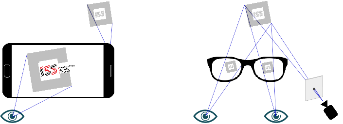
It is cool to see something drawn over the marker on the smartphone screen. But it isn't completely augmented reality. To get complete AR experience, a user should see real objects directly with eyes, not on the screen. AR glasses provide this feature. They contain two small transparent screens: one in front of the left eye, and one in front of the right one. We can draw something on these screens. The user will see it over real objects – this is AR way!
We have used Epson Moverio BT-300 smart glasses. They work on Android 5.0 and have 1280×720 "virtual" screen (actually two 640×720 physical screens).
So, we need to show the project logo and info on these screens. But… where? Remember that on AR glasses a user sees a real object by eye, not on the screen (like on smartphone). The logo and info we show should be aligned with real objects.
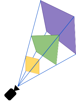
This is a moment where math begins. Math is not provided by ARToolkit. Math called "projective geometry", where every point has a "redundant" coordinate equal to one. This geometry describes relation between the object coordinates in the world and in the camera frame. It can also describe relations between two frames showing the same object from two different perspectives.
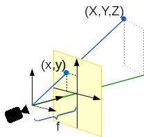
Let's place the world CS origin against the eye. Let's define the distance between the eye and the glasses screen as [math]f[/math]. Similarity of triangles gives [math]x = \frac{X f}{Z}, \; y = \frac{Y f}{Z}[/math].
Now let us move WCS origin to a free position. Now the relation between the screen coordinates [math]\mathbf{x}[/math] and the world coordinates [math]\mathbf{X}[/math] is expressed by the equation [math]\mathbf{x} \parallel P \mathbf{X}[/math], where [math]P[/math] is a 3х4 matrix, [math]\parallel[/math] means equality of two vectors up to scale, also known as collinearity.
To get the exact equality, let's make the third coordinate of [math]\mathbf{x}[/math] equal to one (remember that we are using homogeneous coordinates): [math](x,y,1)^T =\left(\frac{P_1 X}{P_3 X}, \frac{P_2 X}{P_3 X}, \frac{P_3 X}{P_3 X}\right)^T[/math].
Now let's find the [math]P[/math] matrix. To do it, we need multiple pairs of the points [math]\mathbf{x}\leftrightarrow\mathbf{X}[/math]. Each pair fixes the collinearity [math]\mathbf{x} \parallel P \mathbf{X}[/math]. Remember that the cross product of collinear vectors is zero, so [math]\mathbf{x} \times P \mathbf{X} = 0[/math]. This vector equation produces three scalar equations for [math]P[/math] matrix elements. One of these equations is dependent, so, we get two equations for [math]P[/math] from every [math]\mathbf{x}\leftrightarrow\mathbf{X}[/math] pair. The whole 3×4 matrix [math]P[/math] could be found using six pairs of [math]\mathbf{x}\leftrightarrow\mathbf{X}[/math]. These pairs produce the system [math]A \mathbf{p} = 0[/math], where [math]\mathbf{p}[/math] stands for the elements of the matrix [math]P[/math] flattened to a single vector.
This solution is very sensitive to errors. This effect could be decreased by using more than six pairs. It will give the system on [math]P[/math] containing more equations than unknowns (we have twelve unknowns). Such system doesn't have an exact solution. But the approximated one is more robust. This solution could be found by expressing the matrix [math]A[/math] through its singular value decomposition [math]A = U S V^T[/math], where matrices [math]U[/math] and [math]V[/math] are orthonormal, and the matrix [math]S[/math] is diagonal. The elements on its diagonal are sorted in the descending order. After this decomposition the rightmost column of [math]V[/math] is a solution, i.e. [math]p = V(:, end)[/math].
The procedure we used to obtain pairs of points is the following:
| 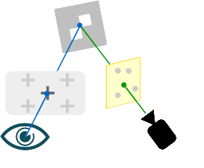 | 1. The user places glasses on his/her head and looks at the target marker; 2. The point appears on the screen. This is the point named [math]x[/math] above; 3. The user moves his/her head to align the point on the screen with the marker and then presses the button; 4. The camera catches the marker position, that is [math]X[/math] point. |
|---|---|
| 1. The user places glasses on his/her head and looks at the target marker; 2. The point appears on the screen. This is the point named [math]x[/math] above; 3. The user moves his/her head to align the point on the screen with the marker and then presses the button; 4. The camera catches the marker position, that is [math]X[/math] point. |
|---|---|
These steps are performed for the left and the right eyes separately. As a result, two matrices [math]P_l[/math] and [math]P_r[/math] are obtained. After passing these matrices to OpenGL, we are able to draw the logo and info in 3D, as we did on the smartphone. But now the image drawn follows the marker directly seen by eye. This is what AR really is – virtual objects follow real ones seen by the user.
All these procedures give the result for a particular person. Having another eye distance or a nose shape, user can't achieve proper alignment between drawn and seen objects.
It is (almost) impossible to perform calibration for every new user. So, we implemented an adjustment function for our app. It allows the user to move the virtual image and change the distance between the left and right images. It works, but it takes a lot of time to explain the user how to achieve the result.
Conclusion
In conclusion, I would like to say that ARToolkit has been a good tool for our first AR project. It covers all major needs of AR developer: marker tracking, 2D-to-3D math, OpenGL interaction.
However, the documentation is a weak part of the project. It was written by the authors of the code, which is why it covers only basic use cases skipping a lot of essential details. The code is often hard to read, especially in the math parts.
So, we studied both the documentation and sources to understand how everything works. Now we are ready to help other developers to start working with ARToolkit or to improve existing code.